


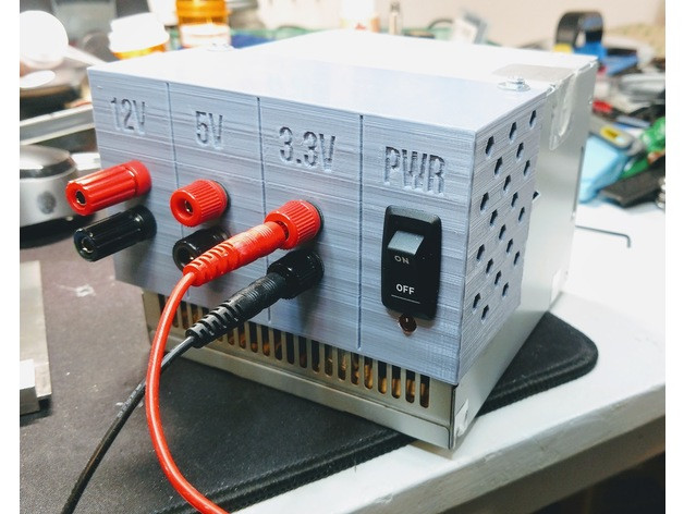
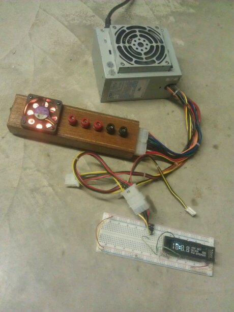
Convert/adapt an old ATX Power Supply into a Bench Power Supply with (or without) 3D Printed Parts
Posted by jpluimers on 2018/11/16
 An interesting idea, although I would slightly modify it so I can -12V and -5V as well and maybe other voltage combinations too:
- [WayBack] Convert an old ATX Power Supply into a Bench Power Supply with (or without) 3D Printed Parts.
- [WayBack] Benchtop power supply with ATX connector
They are based on these underlying links:
- [WayBack] ATX to Benchtop Power Supply by elliotboney – Thingiverse
- [WayBack] Convert ATX PSU to Bench Supply to Power Circuits
Note that some of the newer power supplies with 24-pin molex connectors do not give you -5V any more.
A few notes:
- depending on the age, ATX supplies can get you these voltages: -12V, -5V, 0V, +3.3V, +5V, +12V
- -12V and -5V have very limited currents
- newer power supplies often do not have -5V (especially the ones having 24-pin connectors)
- newer power supplies have limited +5V power, but higher +12V power
- older power supplies have limited +12V power, but higher +5V power
- always take pictures of all connectors and the wire colours connected to them before starting (especially before cutting any wires)
- this allows you to find back:
- non-standard wire colours
- configurations not covered here
- this allows you to find back:
- to get stable 12V, you need a 5V load of about 5W:
- between RED (+5V) andBLACK (GND),
- for instance with pin 3 and pin 4,
- or over one of the molex/floppy connectors: pins RED-BLACK
- as load,
- use at least a 10V/10W resistor or 12v/10W halogen lamp
- ensure they are cooled well
- to get stable 12V, you need a 12V load of about 10W
- between YELLOW (+12V) andBLACK (GND),
- for instance with pin 10 and pin 17,
- or over one of the molex/floppy connectors: pins YELLOW-BLACK
- as load,
- use at least a 20V/20W resistor or 12v/20W halogen lamp
- ensure they are cooled well
 if your power supply has a BROWN (+3.3VS),
- then ensure it is connected to ORANGE (+3.3V)
- as brown is the SENSING wire to check 3.3V is OK.
- then ensure it is connected to ORANGE (+3.3V)
- to turn the power supply on,
- short GREEN (PWR_ON, pin 14) and BLACK (GND, pin 15)
- to know when the power is on:
- connect a LED via a resistor between GREY (PWR_OK, pin 8) and BLACK (GND, pin 7)
- to know when there is mains power:
- connect a LED via a resistor between PURPLE (+5VSB, pin 9: stand by) and BLACK (GND, pin 7 or pin17)
- Wikipedia: ATX Power supply describes
- PWR_OK (often called Power Good)
- +5VSB (stand by)
- read the specs of your power supply to understand how much current it can deliver on which lines
- some more current information
- [WayBack] Power spec for the PCI-E 8 pin power plug – [Solved] – Components
- PCI-E 6 pin: Pins 1 & 3 are 12V & each can carry 8 A, totaling 12V*8A*2= 192W
- PCI-E 8 pin: Pins 1,2,3 are 12V & each can carry 8 A (before ~ March 2005) or 11 A (after ~ March 2005), totaling 12V*8A*3=288 W or 12V*11A*3=396W
- It also explains why not all pins in these connectors are connected or can carry current.
- Not just the connector, also the wires matter: American wire gauge: Tables of AWG wire sizes (and A rating)
- To get a feel read [WayBack] Using PC power supplies in things other than PCs and the pages he links to (see list further below)
- [WayBack] Power spec for the PCI-E 8 pin power plug – [Solved] – Components
Example for loads: https://www.youtube.com/watch?v=gKgziA46wFY; more on why you need them and how to choose:
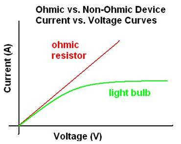 [WayBack] How to calculate suitable dummy load for a power-supply?
- [WayBack] PC Power Supply – Power supplies (PSUs) built for commodity PCs, typically ATX PSUs – Base Load
- [WayBack] ATX power supply 5V load resistor for better 12V regulation
- [WayBack] Converting an ATX Power Supply Into a DC Bench Supply
- [WayBack] ATX to Lab Bench Power Supply Conversion
- [WayBack] ATX Based Lab Power Supply
- Don’t choose the wrong resistor… [WayBack] Convert an ATX Power Supply Into a Regular DC Power Supply!
With a few more modifications you can [WayBack] Convert a Computer Power Supply to a Variable Bench Top Lab Power Supply.
I will probably go for this solution as it is easier to swap power supplies.
–jeroen
Via: [WayBack] Nice recycling of an old ATX power supply with a 3D printed part and a few accessories and cables… – Jean-Luc Aufranc – Google+
[WayBack] Using PC power supplies in things other than PCs
Via: [WayBack] What is the power specification for SATA?
- [WayBack] Using PC power supplies in things other than PCs
- [WayBack] Compatibility issues for ATX power supplies and motherboards
- [WayBack] A short history of PC power supply voltage rails
- [WayBack] So what’s all this rubbish about multiple 12 volt rails?
- [WayBack] All about the various PC power supply cables and connectors
- [WayBack] Rail complications #1 – current limit problems: too much current
- [WayBack] Rail complications #2 – cross loading problems: unbalanced current
- [WayBack] Rail complications #3 – minimum loading problems: too little current
Details:
- [WayBack] All about the various PC power supply cables and connectors (it has tables with the various part numbers including ones for parts of connectors and unofficial current/wattage that I’ve quoted below)
- [WayBack] oldpc: Original PC main power cables
- [WayBack] peripheral: 4 pin peripheral power cable
5A per line; one 5V line; one 12V line
(The connector is often called “Molex”, but actually is AMP Mate-N-Lok; Molex has tons of different connects, one of which is now compatible with the AMP one) - [WayBack] floppy: Floppy drive power cable
3A per line; one 5V line; one 12V line - [WayBack]aux: 6 pin auxiliary power cable
10A per line; two 3.3V lines; one 5V line - [WayBack] sata: SATA power cable
1.5A per line; three 3.3V lines; three 5V lines; three 12V lines
(3.3V is often not connected) - [WayBack] atxmain20: ATX 20 pin main power cable
6A per line; three 3.3V lines; four 5V lines; one 12V line - [WayBack] atxmain24: ATX 24 pin main power cable
6A per line; four 3.3V lines; five 5V lines; two 12V lines
(most PSU with the 24-pin connector omit the -5V lead from it) - [WayBack] atxmain20plus4: ATX 20+4 pin main power cable
6A per line; four 3.3V lines; five 5V lines; two 12V lines - [WayBack] atx12v4: 4 pin ATX +12 volt power cable
8A per line; two 12V lines
(note it looks similar to the “plus 4” from the “20 plus 4”, but is different as the 12V4 has only 12V) - [WayBack] eps8: 8 pin EPS +12 volt power cable
7A per line; four 12V lines - [WayBack] eps4plus4: 4+4 pin +12 volt power cable
7A per line; four 12V lines - [WayBack] pciexpress: 6 pin PCI Express power cable
8A per line; two 12V lines (sometimes three 12V lines) - [WayBack] pciexpress8:
8A per line; three 12V lines - [WayBack] pciexpress6plus2: 6+2 pin PCI Express power cable
8A per line; three 12V lines
PC Power Connectors
How to Convert ATX PSU (PC power supply unit) into a cheap bench top power supply which can be used to power many different types of electronics circuits
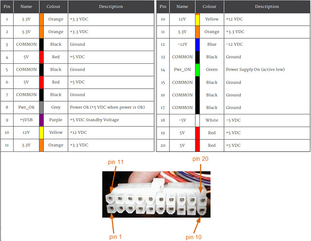
20 pin molex connections
| Pin | Name | Colour | Description | |
| 1 | 3.3V | Orange | +3.3 VDC | |
| 2 | 3.3V | Orange | +3.3 VDC | |
| 3 | COMMON | Black | Ground | |
| 4 | 5V | Red | +5 VDC | |
| 5 | COMMON | Black | Ground | |
| 6 | 5V | Red | +5 VDC | |
| 7 | COMMON | Black | Ground | |
| 8 | Pwr_Ok | Grey | Power Ok (+5 VDC when power is Ok) | |
| 9 | +5VSB | Purple | +5 VDC Standby Voltage | |
| 10 | 12V | Yellow | +12 VDC | |
| 11 | 3.3V | Orange | +3.3 VDC | |
| 12 | -12V | Blue | -12 VDC | |
| 13 | COMMON | Black | Ground | |
| 14 | Pwr_ON | Green | Power Supply On (active low) | |
| 15 | COMMON | Black | Ground | |
| 16 | COMMON | Black | Ground | |
| 17 | COMMON | Black | Ground | |
| 18 | -5V | White | -5 VDC | |
| 19 | 5V | Red | +5 VDC | |
| 20 | 5V | Red | +5 VDC | |
24-pin molex connections
| Pin | Name | Colour | Description | |
| 1 | 3.3V | Orange | +3.3 VDC | |
| 2 | 3.3V | Orange | +3.3 VDC | |
| 3 | COM | Black | Ground | |
| 4 | 5V | Red | +5 VDC | |
| 5 | COM | Black | Ground | |
| 6 | 5V | Red | +5 VDC | |
| 7 | COM | Black | Ground | |
| 8 | Pwr_Ok | Grey | Power Ok (+5 VDC when power is Ok) | |
| 9 | +5VSB | Purple | +5 VDC Standby Voltage | |
| 10 | 12V | Yellow | +12 VDC | |
| 11 | 12V | Yellow | +12 VDC | |
| 12 | 3.3V | Orange | +3.3 VDC | |
| 13 | 3.3V | Orange | +3.3 VDC | |
| 14 | -12V | Blue | -12 VDC | |
| 15 | COM | Black | Ground | |
| 16 | Pwr_ON | Green | Power Supply On (active low) | |
| 17 | COM | Black | Ground | |
| 18 | COM | Black | Ground | |
| 19 | COM | Black | Ground | |
| 20 | -5V | White | -5 VDC | |
| 21 | +5V | Red | +5 VDC | |
| 22 | +5V | Red | +5 VDC | |
| 23 | +5V | Red | +5 VDC | |
| 24 | COM | Black | Ground | |


DJEBLI said
Good work
To protect the ATX again short circuit. It will be better to connect the Green wire (power on) to Relay contact with black wire. And to energize the relay with the 12 v or 5 v accorditly.
jpluimers said
I’m curious about your idea.
How would that relay be powered?
Dominik Kwolczak said
Seems very interesting!