They are much stronger than plastic threads, no matter how you create the plastic threads.
To make them even stronger, add shell thickness to the thread locations, either globally or by using modifier meshes. Modifier meshes work way better in Cura than in Slic3r.
8GB MicroSD Card with pre-installed FriendlyCore Ubuntu
Screws and screw driver
NanoPi NEO2 quick start guide
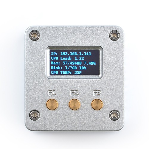
The NanoPi NEO2 LTS (Long Term Support) is a super tiny ARM board made by FriendlyElec and uses Allwinner’s 64-bit H5 quad-core SoC (ARM Cortex-A53). It has internal hexa-core Mali450 GPU and 512MB DDR3 RAM.
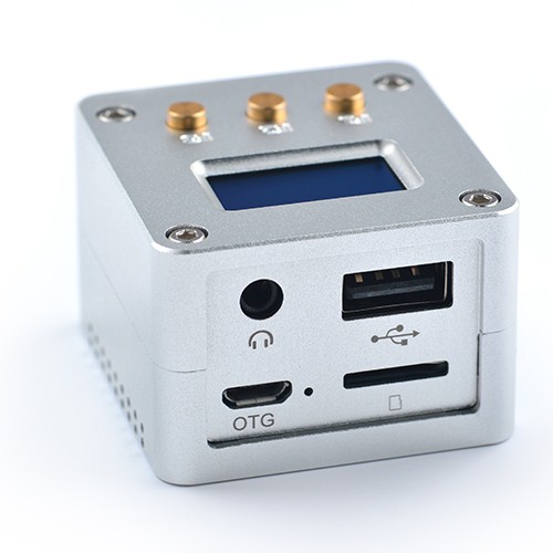
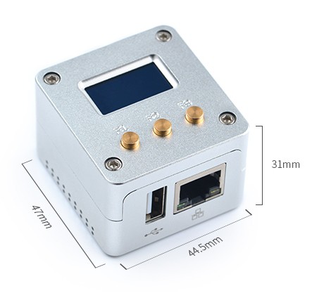
The NanoPi NEO2 has Gigabit Ethernet and one USB host port. These features make it especially suitable for applications that require high data throughput, high-speed data transmission and high performance.
Schematics show it uses an LM317 linear voltage regulator (to get 5V out of a 8V-35V range) next to the ACS712 current sensor (based on the [WayBack] Hall effect) available in 5A, 20A and 30A varieties.
When connecting NeoPixels to any live power source or microcontroller, ALWAYS CONNECT GROUND (–) BEFORE ANYTHING ELSE. Conversely, disconnect ground last when separating.
Adding a 300 to 500 Ohm resistor between your microcontroller’s data pin and the data input on the first NeoPixel can help prevent voltage spikes that might otherwise damage your first pixel. Please add one between your micro and NeoPixel.
Before connecting a NeoPixel strip to ANY source of power, we very strongly recommend adding a large capacitor (1000 µF, 6.3V or higher) across the + and – terminals. This prevents the initial onrush of current from damaging the pixels.
Be extremely cautious with bench power supplies. Some — even reputable, well-regarded brands — can produce a large voltage spike when initially switched on, instantly destroying your NeoPixels!
If you use a bench supply, do not connect NeoPixels directly. Turn on the power supply first, let the voltage stabilize, then connect the pixels (GND first).
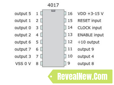
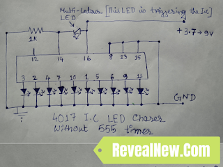
The triggering in this case is the result of a main power drop and recover. The battery is unable to keep the votage at 9V level at the very moment any led is turned on, the voltage is droped down. That is what makes pin 14 to get the clock pulse so the 4017 shifts to the next led. The moment the led is off and right before the next led is turned on the main power gets recovered. When the next led is on again, the main power drops down, and so on.