One of the most common upgrades for any Haswell (xx40) series ThinkPad is to replace the awful button-less touchpad (sometimes referred to as the ClunkPad) with a T450 touchpad that has the proper buttons for TrackPoint users. However, getting the buttons to work properly on xx40 hardware can be tricky – particularly if you are running Windows 10. In this video you will see how to get drivers installed that will allow you to use the TrackPoint as if this were a T450! As always thanks for watching! Some of the guides I used for this video:
I have edited the link so they show forum post titles, added way-back links, and added some crucial information:
PLEASE NOTE:
BEFORE YOU PUT IN THE NEW TOUCHPAD, INSTALL SOME EXTRA BUMPERS/RUBBERS ALONG THE TOP OF THE LID, LEFT AND RIGHT OF THE WEBCAM.
THESE SHOULD BE ABOUT TWICE AS THICK/HIGH AS THE SMALL BUMPERS THAT ARE THERE ALREADY.
Recommended size ~WxH: ~6 x 2 mm or ~1/4 x 5/64 inch.
PLACE THEM IMMEDIATELY LEFT AND RIGHT OF THE EXISTING BUMPERS.
FAILURE TO DO SO WILL RESULT IN SCRATCH MARKS ON THE SCREEN FROM THE NEW BUTTONS!
The signal quality fluctuates during the day (it is a lot better at night when there is less inionisation in the atmosphere), and is worsened by concrete walls (like our home).
Best way to get prolonged reception is at night, on the top floor behind a window or outside.
The clock usually needs between 3 and 10 minutes to pick up the DCF77 signal from the transmitter.
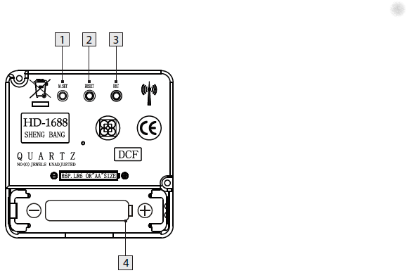
Press and keep pressed the M.SET button 1 at least 3 seconds. The wall clock switches into manual mode.
Press and keep pressed the M.SET button again until the hands reach the correct position for you to set the time.
Briefly pressing the M.SET button moves the hands forward in one minute steps to enable you to set the current time manually.
Note: After 8 seconds without pressing the M.SET button, the wall clock switches out of manual mode and keeps the time as normal. The manually set value is overwritten as soon as reception of the DCF radio time signal is successful.
RESET button
Press the RESET button 2 to reset the radio clock settings. Alternatively, remove the batteries from the device and insert them again.
The product now automatically starts to search for the DCF radio time signal.
REC button
Press and keep pressed the REC button 3 at least 5 seconds. The wall clock attempts to receive the DCF radio time signal. This process takes a few minutes to complete.
Battery compartment
Battery type: 1 x 1.5 V ⎓ AA, LR6
More on the signal, transmitter and encoding: DCF77 – Wikipedia, where the below images are from:
DCF77 reception area from Mainflingen
DCF77 signal strength over a 24-hour period measured in Nerja, on the south coast of Spain 1,801 km (1,119 mi) from the transmitter. Around 1 AM it peaks at ≈ 100 µV/m signal strength. During the day, the signal is weakened by ionization of the ionosphere due to solar activity.
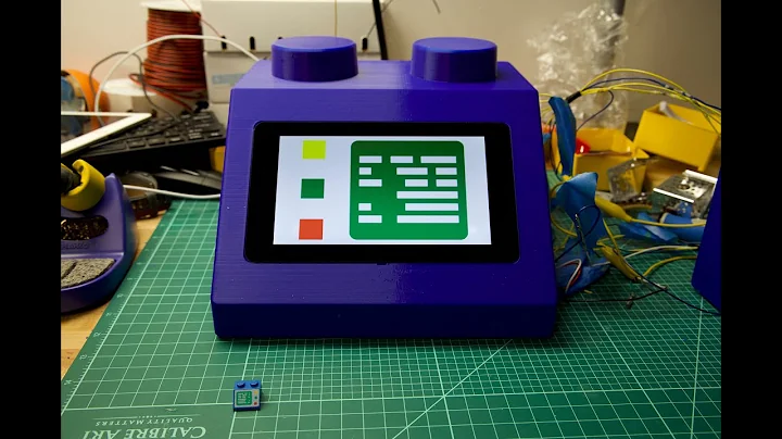
a simple PCB in a small case where you plug the phone in
…
The completed project works very simple:
Pick up the phone, you hear the “dial tone” MP3, Dial a number, you hear the MP3 0..9 playing (depending on the dialed number), When the song is over, you hear the “disconnected” MP3, You can dial another number and hear another song or hang up the phone.
Some phones also have a button on the front. When you press this button, the phone randomly playes one of the songe 0..9 and when that song is over, it automatically plays a new song, randomly. This will allow the person on the phone to continuously listen to the music. This may be of help to those who can’t figure out how it works but love to hear the songs over and over again.
You can configure the music folder from which the MP3s are played, you can use up to 10 different folders
You can configure the volume of the device
Configurations are done through the phone itself (dial 738 OR hold the button while picking up the handpiece), you hear a voice that guides you through a menu and all you need to do is dial in your settings value.
You can power this design through a USB port cable. This way the device can be fed using a simple mobilephone charger OR be connected to the PC. When connected to a PC, the TeleJukebox identifies itself like a USB-stick and you can easily modify the file without removing the card from the system. Meaning that you do no even need to open the case in order to change the collection of MP3 files. Keep in mind that when the device is in USB-stick mode, it cannot playback MP3 files meaning that in this mode it will not act like a TeleJukebox.
Music rights
Especially when using this in a professional environment. be sure the music that plays is rights free (there are music therapists for treating people with Alzheimer’s and dementia that can help you with that).
Steps, reasoning, and building instructions
A less in depth Dutch article (with 13 minute explaining video below) explaining most of the steps and all the reasoning is this multi-part one:
Note that the most recent Wonderfoon products got more versatile allowing more songs, warnings for taking pills, and ring-reminders based on morse code.
Make sure your tv supports cec and that it is enabled. Tv manufactures call CEC by different names so you may have to do some research depending on your brand.
Make sure you are using a new hdmi cable that is at least HDMI 1.2a
Different names for HDMI CEC
Samsung – Anynet+
Sony – BRAVIA Link or BRAVIA Sync
Sharp – Aquos Link
Hitachi – HDMI-CEC
AOC – E-link
Pioneer – Kuro Link
Toshiba – Regza Link or CE-Link
Onkyo – RIHD (Remote Interactive over HDMI)
LG – SimpLink
Panasonic – VIERA Link or HDAVI Control or EZ-Sync
In the past I had these manual scripts to power-cycle a hung RaaspberryPi device:
/interface ethernet poe set ether5 poe-out=off
/interface ethernet poe set ether5 poe-out=forced-on
or on one line:
/interface ethernet poe set ether5 poe-out=off; /interface ethernet poe set ether5 poe-out=forced-on
I am going to try this script for the port having a Raspberry Pi on it (note: this requires a 48V power brick for the Mikrotik!) on RouterOS version 6.48.3 (stable):
Note that I did disassemble both of these routers for inspection and there are obvious changes to the hardware to correct the PoE problems – most notably a completely different relay, capacitor and some minor circuit design changes.
:local ipPing ("x.x.x.x")
:local pingip
#
# pingip below RUNS and sets the variable
# to number of successful pings ie 3 means 3 of 45 success
# can also use ($pingip > 1) or ($pingip >= 1) both TESTED
# ($pingip >= 1) means if only 1 or 0 pings do the IF, not the ELSE
#
:log info ("ping CHECK script IS RUNNING NOW")
# first delay 90 b4 ping test incase this is running at POWER UP
:delay 90
:set pingip [/ping $ipPing count=45]
:if ($pingip <= 3) do={ :log warning (">95% lost ping LOSS to isp GW IP x.x.x.x via ether5 so DO POE powerCYCLE")
  /interface ethernet poe set ether5 poe-out=off
  :delay 12
  /interface ethernet poe set ether5 poe-out=auto-on
  :delay 10
  :log warning ("ether5 POE HAS BEEN TURNED BACK ON")
  :delay 90
  /system script run emailPOEresult
} else={
  :log warning ("PoeCyclePINGcheck ELSE ran so no ping loss detected by script")
}


:strip_exif()/i/2003591010.jpeg?f=imagegallery)
:strip_exif()/i/2003591190.jpeg?f=imagenormal)
:strip_exif()/i/2003591198.jpeg?f=imagenormal)
:strip_exif()/i/2003591196.jpeg?f=imagenormal)
:strip_exif()/i/2003591184.jpeg?f=imagegallery)
:strip_exif()/i/2003591182.jpeg?f=imagegallery)
:strip_exif()/i/2003591160.jpeg?f=imagegallery)
:strip_exif()/i/2003591162.jpeg?f=imagegallery)
:strip_exif()/i/2003591164.jpeg?f=imagegallery)
:strip_exif()/i/2003591166.jpeg?f=imagegallery)
:strip_exif()/i/2003591182.jpeg?f=imagegallery)
:strip_exif()/i/2003591186.jpeg?f=imagenormal)
:strip_exif()/i/2003591204.jpeg?f=imagenormal)


